The Science Behind the Other Science Fiction Staple: Railguns
- Aug 13, 2018
- 13 min read
Updated: Oct 12, 2023
Written by Harry J. (GAFL'19)
Edited by Chloe C. (VHS '21)
━━ August 12th, 2018 ━━

Railguns
In almost any narrative of a science-fiction based action movie, novel, etc., one can find mention of railguns quite easily (with the notable exception of Star Wars). This glaring omission notwithstanding, it is evident that, along with lasers, railguns are an indispensable component of the science fiction arsenal. But, as often as not, railguns are grossly misrepresented in form and function - as in the case above, in a scene taken from Michael Bay’s Transformers 2 - and the purpose of this article is to correct the misconceptions that may arise as a result by investigating the actual physical principles that govern the mechanics of a railgun.
Kinetic Energy and Weapons

To understand a railgun, we will first take a look at its primary use: war. On a tactical scale, armed combat is essentially an exercise of how much destructive energy can be transferred to the opponent’s assets before one’s own are neutralized or a decisive victory is achieved. Guns and cannons fulfill this purpose by firing projectiles at targets. This is achieved by deflagrating a propellant in a component of the gun known as the chamber - the high pressures that result from this deflagration transfers energy to the projectile, which is pushed out of the barrel. From an energetic perspective, one can view it as chemical energy stored in the chemical bonds of the propellant being converted to kinetic energy of the projectile, energy which is in turn transferred to the intended target, causing damage by inducing deformation and structural stresses.
Historically, while chemical propellants such as gunpowder or the more modern cordite have proved effective, it nevertheless has its drawbacks - modern ammunition carries this propellant in cases attached to the bullet, adding mechanical complexity and weight to the apparatus as a whole. Moreover, during combat, the combatant is burdened with the extra weight of the propellant. This goes for vehicles and naval vessels as well - especially for armored vehicles such as tanks, which have additional explosives in their warheads, ammunition is a major hazard for crew as impact on any of their components can detonate them. In short, ammunition with chemical propellants are heavy, complex and dangerous. Railguns, on the other hand, are devices that convert electrical energy straight to kinetic energy. This negates the need for explosive propellant, and by extension, reduces weight devoted to ammunition.
More than safety, however, there exists a more important distinction, and this is the energy the projectile can transfer. Kinetic energy is defined as [(mv^2)/2], or one-half of the mass times the velocity squared (measured in Joules, or J). For a given velocity, an object with higher mass will have more energy, and for a given mass an object with a higher velocity will have more energy. For conventional chemical-propellant projectiles, there is an upper limit to this velocity at about 1000 m/s, or about Mach 3; no propellant or bullet exists that can possibly go faster, be it rifle or cannon, at least with chemical propellants. By contrast, railguns are capable of attaining muzzle velocities of up to 2000~3500 m/s, or Mach 7. This means, for the same mass, a projectile fired from a railgun will have more energy due to its higher velocity. (Since railguns

attain more than twice the velocity of conventional guns, and kinetic energy is proportional to velocity squared, for the same projectile railguns will outperform conventional guns in terms of energy by at least a factor of 4.) Shown right is a high-speed photograph of a projectile fired from a railgun - notice the bow shock in front of the projectile. The flames behind the projectile is from the ignition of the air due to the high temperatures generated by friction.-
An understanding of how exactly this happens, however, is dependent on an understanding of electric and magnetic forces; as such, before we look through the structure of a railgun, we will look through what physical laws allow the railgun to operate.
Electricity and Magnetism
- Electromagnetism:

This is the core of everything that we rely on to power our homes. Until the development of Maxwell’s equations, which united them into a common phenomenon, electricity and magnetism were originally considered completely separate concepts. The presence of an electric charge will produce an electric field; the movement of these charges through a medium, or an electric current, produces a magnetic field. As a general rule, electricity is considered to flow from the positive side to the negative side. While electricity has various uses, such as in consumer electronics, we will be primarily concerned with its role in generating power.
- Magnetic field around a current-carrying wire:
We mentioned that an electric current will create an electric field. To be more specific, a current (denoted by I) traveling through the wire will create a magnetic field around it (denoted by B) in a clockwise direction (based on a current pointing into the imaginary clock). A useful way to visualise this is through the right-hand rule. Imagine you are grasping the wire with your right hand. The direction your fingers curl when you close your fist will be the direction of the magnetic field. As we will find out, the generation of such a magnetic field is crucial to the operation of a railgun.
- The strength of this magnetic field (measured in Teslas, or T) is given by B=(μL)/2πr, where μ is the permeability of a medium (how easily a magnetic field permeates the medium), L is the length of the wire in meters, and r is the distance from the wire.
- Force: Courtesy of Newton’s second law, we define force as F=ma, or Force = mass * acceleration. A force applied on a given mass will cause it to accelerate at a rate a.
- Force on a current-carrying wire: As it happens, when a wire is carrying current, and also in

the presence of a magnetic field, a force (measured in Newtons, or N) will act on it given by the formula F=BIL, where B is the strength of the magnetic field, I is the magnitude of the current (measured in Amperes, or A), and L is the length of the wire. The direction of the force is dependent on the directions of the magnetic field and current - another right-hand rule exists for this situation (this is different from the one we used to find magnetic fields around wires!) Lay your right hand out flat, with the thumb pointing in the direction of the current, and the remaining four fingers in the direction of the magnetic field; the resulting force will push in the direction your palm is facing. This is also known as the Lorentz Force.
And really, this is all the physics you will need to know to understand how railguns work - now, let’s delve into the fun part.
Railguns

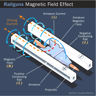
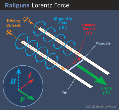
A railgun is essentially no more than a large electric circuit composed of a power source, a pair of conducting rails in parallel (from which railguns get their name) and a sliding, conducting armature, which connects the two rails and carries the projectile. In an actual railgun, the armature will release the projectile at the end of the rails. This is illustrated in detail in the visualization below - note the power source is not explicitly represented, but one can assume its presence by the current (orange arrow) shown flowing through the apparatus. While visually descriptive, the illustration does not exactly give a clear view of how the physics come into effect; we will thus draw a simplified diagram of the circuit, shown below.
We can see that, in their simplest forms, both the rails and the armature can be thought of as current-carrying wires. (The rails are the two longer, parallel wires - the armature is the shorter, perpendicular wire in between.) From a power source, a current is run into the first rail; based on the first right-hand rule, a magnetic field will form around the wire in a direction that has the resultant field between the wires pointing up. The current will then move into the armature, and

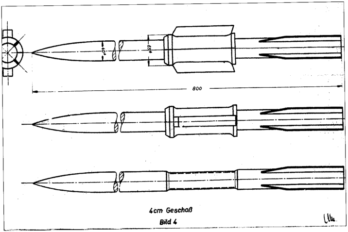
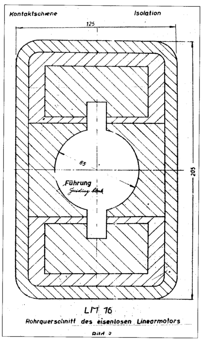
then travel back down the other rail, where, again, according to the right-hand rule a magnetic field will form around the rail that points upwards between the rails. As a result of the current, we have a current running through a circuit that creates a large, vertical net magnetic field pointing upwards between the wires - so what? This is where the last part of the last section comes into play. When a current-carrying wire is perpendicular to a magnetic field, a force will be created. With the second right-hand rule, we can see that with a current traveling sideways and a net upward magnetic field, a force will propel the sliding armature down the rails, accelerating the projectile. (Examples below - early German conceptual illustrations, Left image is barrel cross-section, viewed from front. Note vertical rail arrangement.)

Few people appreciate how elegant of an invention the railgun really is - at its core, it is a remarkably simple concept dependent of the most basic of physics principles. While we’re at it, let’s try and quantify some values, returning to the formulas we had earlier. All values will be a function of current, or I.

We said earlier that B=(μL)/2πr. If we set the distance between the rails as 2r, and the length of conducting rail as L, (note: L will be variable, as the movement of the armature will change the length of rail carrying a current. Calculus will be required, but we won’t do that.) we can get a value for the magnetic field produced by one rail a distance r from the rail (this is directly between the rails, since r is one-half the distance between them (2r)). Since there are two rails, we need only to multiply this by two, giving us a value for the total magnetic field between the rails, B=(μL)/πr.
F=BIL; since B=(μL)/πr, this can be rewritten as F=(μIL^2)/πr. Based on the length of the rails and armature, and the strength of the current, we will have a value for the force exerted on the armature, and by extension, the projectile.

Let’s take it a step further. F=(μIL^2)/πr=ma. The acceleration a will then be (μIL^2)/πmr=a, or the force divided by the mass. At this point, I will invoke some basic kinematics equations; the first being Δx=v(initial)t+(at^2)/2, where t is time measured in seconds. The reason for finding this will become apparent soon. There is no initial velocity and the change in x will, in this case, be equal to the length of the rail L. Therefore, L=(at^2)/2, which will eventually turn out to be L={(μIL^2)*(t^2)}/2πmr. Solving for t, we get (2πmrL)/(μIL^2)=t^2, so t=sqrt{(2πmrL)/(μIL^2)}. (The actual time in a real-life railgun will typically be a fraction of a second - this will require the current to be provided in a very short pulse, hence necessitating advanced capacitors* more than batteries.) Another kinematic equation dictates that v(final)=v(initial)+a*t, where v(initial) is 0, so the final velocity will be the acceleration times the time, both of which we have. (μIL^2)/πmr=a, and t=sqrt{(2πmrL)/(μIL^2)}, so v(final)=at=sqrt{(2μIL^3)/(πmr)}. (I will omit the procedure behind this.) Kinetic energy was (mv^2)/2, and v=sqrt{(2μIL^3)/(πmr)}. As a result, kinetic energy will be KE={m(2μIL^3)/(πmr)}/2 =(μIL^3)/(πr)}, which ends up being a function of the current, rail length, and separation. Note this is a simplified formula, not taking into account the variable length of conducting rail.
Modern Use
Despite its conceptual elegance, it has yet to reach any form of usability in modern warfare because of the immense heat and stress that develops when firing the weapon. To have a railgun fire a projectile with an appreciable level of energy, the required current is frequently in the millions of amps, an immense number considering the average light bulb draws about 0.5 amperes of current. In addition, the massive acceleration the armature and projectile undergoes (typically beyond 60,000g, or 600,000ms^-2) will generate friction between the armature and rails no matter how smooth they are, resulting in lateral stresses and heat that will rapidly erode the rails. Materials science has yet to come up with a material that can withstand these conditions repeatedly, an important milestone considering that railguns today can currently only fire anywhere from several to several dozen shots until their rails erode to unusability.
Active research is being done to rectify this, however. A number of prototypes exist around the world, the most successful of which have attained energies up to 32 megajoules. By comparison, the energy carried by the cannon of an average tank is in the neighborhood of 9~10 megajoules. However, this is at a significant disadvantage in size, as the technology demonstrator in existence now is nearly the size of a naval cannon. Shown below is a U.S. Navy railgun prototype, which has successfully completed several tests since its creation. The U.S., among other countries, hopes to integrate railgun technology into their militaries in the near future. In fact, they - or at least, a derivative form - are already in use on the newer Gerald R. Ford-class aircraft carriers, where electromagnetic accelerators based on the principles of a railgun are used to propel planes off the deck, replacing the older system, which relied on hydraulic pressure**.

Its prospective uses are not limited to warfare - scientists have proposed that similar technology be used to accelerate payloads to high velocities and send them into orbit, complementing rockets in their purpose and capability. The high accelerations associated with railguns, however, will limit this use to only the sturdiest of payloads (unless provided with very long rails). Its use in facilitating nuclear fusion has also been suggested - since railguns can accelerated any conductive material between its rails, it is feasible that this may be done with plasma, which can be pumped into a small chamber from multiple directions to create the high temperatures and pressures required for fusion.
For railguns to ever see use in any of these applications, it will first need to overcome these key technological milestones:
Barrel durability: As the projectile accelerates rapidly through the barrel, it will also generate a small repulsive force between the rails and the armature, creating minuscule gaps between them. Even so, the current will still travel, and small electric arcs will form between them - this has the effect of causing rapid vaporization and damage to the rail surfaces. This limits current rail life to no more than a few shots. Either design considerations must be made so that frequent replacement of the rails is a viable option, or materials science must develop to the extent that the rails can be made out of something that can withstand the said conditions.
Heat dissipation: The immense currents and residual friction from the movement of the armature will generate immense quantities of heat in the barrel, and this presents threats to equipment longevity as well as crew safety. Heat also generates a large infrared signature, increasing the chances of detection by an enemy. For railguns to be used consistently and safely, a method must be devised to efficiently dissipate heat.
Projectile guidance: Railgun projectiles, in order to be able to strike reliably at long-range targets, will require guidance systems to be incorporated with them. This will require an electronics package with exceptionally rigorous design requirements, needing to survive environments with up to 60,000 g’s of acceleration, electromagnetic fields of up to 2 Teslas, and surface temperatures of up to 800 degrees Celsius, all while fitting inside the small dimensions of the projectile without altering its center of gravity.
Also, in general, there will be a number of design limitations that come with railguns. Due to the railgun’s complete reliance on power and capacitors, it will only be mounted on a vehicle or an emplacement that can provide these. As such, the most likely, immediate development is their placement on naval vessels, which will have the surplus current to handle the needs of railguns. For mobile ground troops, however, co-locating an additional electric power supply for every gun will prove unwieldy - handheld railguns are, as of now, purely fictional unless soldiers lugs around a cart of batteries and capacitors with them, a solution that is neither convenient nor survivable. Unless capacitors and batteries with a higher energy density are developed, railguns will remain large weapons mounted on large vehicles.
In addition, the presence of rails will require long and heavy barrels - this, however, is more than negated by the fact that for the same barrel length, railguns will deliver far more destructive energy than a conventional firearm.
Since, for the time being, railguns will be used within our atmosphere, it is inevitable that energy is lost to air resistance - it is projected that a railgun projectile will lose up to half its kinetic energy from air resistance. This is an inevitable consequence, but considering chemical-based firearms suffer from the same limitation, there will still be a net increase in performance.
Conclusions

It is evident that, despite the simple principles behind its conception, railgun and projectile design is a challenging and difficult task; much research and development will need to go into this technology before it can ever completely supplant chemical propellant-based firearms. (Shown above is the aforementioned navy test platform*** firing.) Nevertheless, it is evident that railguns are a technology with a robust background and a bright future, and with time and effort, soon this corner of science fiction, too, will become reality.
Additional Information
*Capacitors: Unlike batteries, which discharge current continuously in a closed circuit, capacitors store charge and discharge it rapidly, making it suitable for applications necessitating short pulses of energy, such as camera flashbulbs and railguns.
**EMALS and aircraft catapults: Because of the limited takeoff distance provided by aircraft carrier decks, it has been necessary to augment aircraft takeoff with a secondary device called a catapult. This is composed of a small pusher behind the front wheel of an aircraft connected to a longer rail below decks; this has typically been done through a steam-piston system, with high-pressure steam from the carrier’s turbines used to accelerate the aircraft fast enough for takeoff. However, this system is inefficient and the rate of force applied is largely out of control. The electromagnetic system, however - dubbed EMALS, or ElectroMagnetic Aircraft Launch System - offers much smoother acceleration, reducing stresses on the airframe, and finer control over the rate of acceleration, allowing it to launch smaller aircraft such as UAVs, which was previously impossible due to the stresses a steam-piston system would induce. In addition, it requires less maintenance, less manpower, less energy, and is by far more reliable than its predecessor; it will also be drastically more efficient, boasting a 90% energy conversion efficiency as compared to 5% for the steam-piston system. EMALS is based on the same principles as a railgun.
***Electro-Magnetic Laboratory Railgun: This US navy prototype (developed in conjunction with General Atomics and BAE Systems) is one of the most successful to date, demonstrating muzzle energies of up to 33 megajoules and a projectile velocity of Mach 7.5 (2570 m/s). An equivalent amount of energy is stored in 5 kilograms of C-4 explosives. This design is capable of launching a projectile to a range of more than 350 kilometers, nearly 10 times the capability of modern naval cannons. If further development is successful, railguns may completely replace conventional cannons in naval and long-range warfare.
━━━━━━━━
Bibliography:
“Electromagnetic (EM) Railgun.” BAE Systems | International, www.baesystems.com/en/product/electromagnetic--em--railgun.
“EMALS.” General Atomics & Affiliated Companies, www.ga.com/emals.
“Future Warfare: Meet The Electromagnetic Railgun.” Futurism, 13 May 2016, futurism.com/future-warfare-general-atomics-railgun-test-lead-truck-mounted-systems/.
Harris, William. “How Rail Guns Work.” HowStuffWorks Science, HowStuffWorks, 8 Mar. 2018, science.howstuffworks.com/rail-gun1.htm.
“Propellant.” Wikipedia, Wikimedia Foundation, 3 Apr. 2018, en.wikipedia.org/wiki/Propellant.
“Railgun.” Wikipedia, Wikimedia Foundation, 5 Apr. 2018, en.wikipedia.org/wiki/Railgun.
Rideout, Kenneth, and Jonathan S. Wolf. AP Physics 1 and 2. Barrons, 2015.
━━━━━━━━


Comments